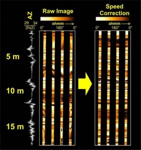
 Logging tools use complex navigation sondes to orient borehole images, and rely on accurate caliper measurements. These require regular preventative maintenance, wellsite calibration and accurate tool string information to provide an image which can be reliably used for any kind of interpretation. Experienced staff at Task Fronterra Geosciences process and QC borehole images from all major services companies, checking for items such as caliper calibration, data delay offsets and formation image integrity.
The Task Fronterra workflow is designed for all types of borehole images including single wireline image, dual wireline image and LWD data. For a more detailed explanation of the processing and QC services we offer, please click here.
Borehole Image Logs can provide an in-depth understanding of the geological setting of a well. They can provide in-situ stress, structural and stratigraphic information, and can be used from the placing of a lateral to helping place frac stages. However, like with any analysis, the value of the final product is related to the quality of the input data.
The logging tools use complex navigation sondes to orient the images, and rely on accurate caliper measurements. These require regular preventative maintenance, wellsite calibration and accurate tool string information to provide an image which can be reliably used for any kind of interpretation.
Task Fronterra’s workflow includes checking the following items:
- Data format and content
- Tri-axial magnetometer and accelerometer data
- Z-axis accelerometer and timing curve
- Caliper calibration
- Data delay offsets
- Depth match
- Orientation offsets
- Formation image integrity
In recent years the quality of data received has reduced, with typically 45% of data provided containing some kind of issue preventing an accurate analysis. Without comprehensive quality control many of these issues will go un-noticed. What causes these problems? Some examples of the causes are:
- Magnetized centralisers
- Complex calibration procedures
- Customer tapes missing information
- Tool offsets poorly or not recorded
- Transducers incorrectly mounted on tool
- Incorrect downhole recalibration
- Curve mnemonic changes
