A Discrete Fracture Network (DFN) model is a mathematical representation of fracture characteristics for hydraulically relevant fractures. We divided our DFN Workflow into the following four main components, illustrating our unique approach:
- Consistent Structural and Stratigraphic Model
- Integrated Fracture Characterization
- Static DFN Model Construction
- DFN Dynamic Validation and Upscaling
Consistent Structural and Stratigraphic Model
Instead of rushing into DFN static construction, several professionals with expertise in various disciplines co-operated in defining a plan for the stages that follow:
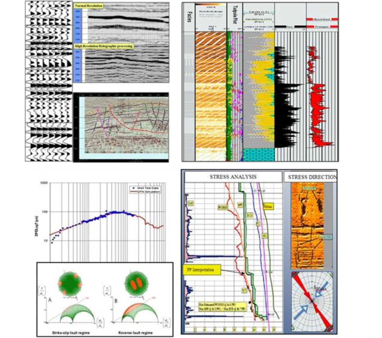
- Borehole image (BHI) data provides detailed fracture characteristics and refined fracture corridors in the borehole vicinity. It enables the recognition of mechanical stratigraphy and in-situ stress states and identifies critically stressed features.
- Open-hole logs complement relationships with BHI fractures and sedimentological analyses, providing facies identification and matrix and fracture porosity estimation.
- Seismic interpretation establishes the structural framework for horizons and faults. Attribute analysis (e.g. coherence and curvature) further support the establishment of fracture density drivers.
- Structural restoration and resulting paleotopography models visualize the different deformation stages of the hydrocarbon system in 3D and enable creating stress and strain maps for the different formation tops (additional fracture density drivers).
- Geomechanical analysis provides mechanical properties, stress characterization and identifies critically stressed features in mechanically relevant layers or blocks.
- Detailed dynamic data analysis (well tests, interference tests, production data) and a material balance model further help to understand the reservoir’s flow behaviour and drive.
- A static matrix model is then established honouring all available input data. The simplifications implemented in the design highly depend upon the conceptual formulation and allow treating complex settings in a more appropriate way. After the creation of the structural framework including all reservoir relevant faults, a detailed facies and petrophysical (matrix porosity and permeability, and water saturation) model can be simulated. Further upscaling, if required, is conducted in close collaboration between the reservoir engineer and the geomodeler incorporating the results of the rock typing analysis.
Integrated Fracture Characterization
TASK Fronterra uses seismic, outcrop, BHI, core, petrophysical logs, structural restoration, geomechanical analysis and production logs to perform an integrated fracture characterization, to ensure the consistency in the spatial distribution of fractures and fracture sets with regard to dynamic reservoir performance.
- Cumulative Fracture Intensity (CFI) analysis is first performed to discover the domains for each fracture set. Volumetric intensity multivariable regression is used for each fracture set to identify fracture generating drivers (e.g. seismic attributes, facies, matrix parameters, stress and strain ,maps and mechanical properties).
- The description and interpretation of the fracture network from BHI, core, outcrop and seismic (fault) must be consistent. Intensity, orientation and size distribution are evaluated.
- Production logs can be used to validate the location and characteristics of the fracture network. Pressure tests and production analysis may complement the dynamic validation for areas away from wells.
Static DFN Model Construction
After the upscaled facies and petrophysical models are loaded, stochastic processing of multiple realizations are used to evaluate uncertainties and risks and to explicitly represent and visualize key discrete fractures in 3D space. Several fracture data analysis tools are then applied to ensure the geological consistency between the model and fracture characterizations, e.g. CFI analysis for the model. Fracture connectivity is analysed for the volumetric estimation.
DFN Dynamic Validation and Upscaling
The dynamic validation and DFN upscaling process is performed on the same platform as the DFN model construction to improve efficiency. Well testing provides best information on the nature of the fracture network away from the well and into the reservoir. Pressure derivative curves are good indicators of the nature of a fracture network. The existing well tests are “history matched” to fine tune the intrinsic permeability parameters for the fracture network. Under appropriate testing conditions, the inter-porosity flow coefficient and fracture storativity parameters can be derived from well test inrerpretation, which are used to calibrate DFN model porosity and permeability values.
DFN dynamic validation is done at well level for well testing but using the field scale model, avoiding the construction of well-scale models. This workflow substantially improves efficiency of the dynamic validation process. This further allows the best means for proving correctness of DFN by matching both the pressure and pressure derivative curves simultaneously, which process ensures that the DFN has correct geometry and connectivity and correct flow properties.
Upscaling of the DFN model to a geocellular model represents the step required to move from discrete to continuum representation of the systems which are required by reservoir simulation. The generated geocellular matrix and fracture model can finally be history matched based on the available production data.