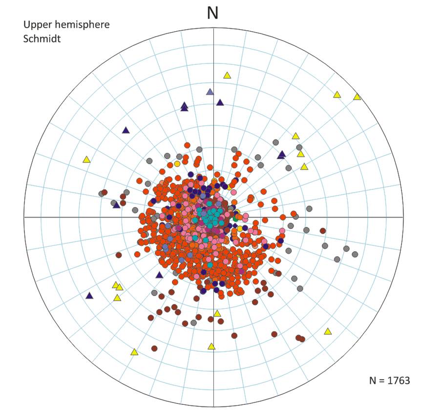
 Stereonets are a graphical tool representing the hemisphere of a globe, used for presentation, analysis and interpretation of three-dimensional directional data such as planes and lines. A stereonet allows the stereographical projection of three-dimensional information onto a two-dimensional plane (usually as a piece of paper or computer image) and is used as a tool applied to a range of geological problems including the removal of structural tilt. Stereonets involve the projection of lines or planes onto a sphere; two alternative projections are commonly used, the upper and lower hemisphere respectively, with use depending on the discipline of interpretation. See example to the left.
Projections are usually completed on pre-formatted nets. Consider a transparent sphere with an extended plane (or line) passing through its centre. A plane will cut the sphere forming a line (great circle) on the sphere’s surface, whereas a line will generate a point. When the sphere is viewed from above these are stereographical projections. As the lines and planes extend beyond the sphere, intersections in the upper and lower hemispheres are visible. The standard projection in the hydrocarbon industry is the upper hemisphere, in contrast to the lower hemisphere projection usually used by structural geologists. The upper hemisphere projection has the advantage that poles to planes plot in the field to which they dip. A pole to a plane is the projection of a line sat perpendicular to that plane. For example, a plane dipping to the southwest has a pole that plots in the southwest quadrant of an upper hemisphere stereoplot. This allows ready visualisation of planar spatial data distributions recorded as tadpoles. The upper hemisphere projection is favoured by students of crystallography.
Stereonets are used in a range of analysis and interpretation of dipmeter and image data. Some applications include:
- Core goniometry,
- Derivation of structural tilt,
- Dip population discrimination,
- Removal of structural tilt,
- Fold analysis,
- Fitting of great circles to data sets to determine axes of rotation,
- Fault and fracture analysis,
- Plotting of borehole directions,
- Bulk presentation of oriented data,
- Sediment dispersal analysis,
- Palaeoslope analysis,
- Detection of anomalous dips,
- Constraining possible structural tilt between two wells sections for a given stratigraphical horizon with known positions,
- Determining the line of intersection of two planes,
- Determination of the angle between two planes,
- Determination of true dip from two apparent dip measurements,
- Detection of borehole bias,
- Deriving likely bedding orientations from maximum apparent dip observed from within core,
- Rigid block stability,
- Estimating stress directions.
Stereonets come in two main types, equal angle Wullf net and as an equal-area Schmidt (Lambert) net. Although both nets can be populated with spatial data and analysed, in some circumstances they differ in utility. Equal-area (Schmidt) nets are used when contouring of data points is required, and when constructions involve small-circles the Wulff net is more useful. Computers have reduced the burden of the hand plotting, contouring and analysis of data, although to gain an understanding of stereonets and there use, conventional manual drawing using tracing paper and drawing pins is essential at the outset of a geologist’s career.
LEYSHON. P. R. and LISLE, R. J. 1996. Stereographic Projection Techniques in Structural Geology. Butterworth-Heinemann, Oxford, p104.
PRIEST, S. D. 1993. Discontinuity Analysis For Rock Engineering, Chapman & Hall, London, p473.
HOWARTH, R. J. 1996. History of the stereographic projection and its early use in geology. Terra Nova, 8, 499-513.
See also mean direction, azimuth vector plot, Hurley plot, rose diagram, dip orientation nomenclature, tangent diagram, tadpole plot, poles to planes, dip and apparent dip.